GaN vs silicon is the choice between two power-transistor materials: gallium nitride, a wide-bandgap compound with a 3.4 eV bandgap and about 11 times silicon’s critical electric field, and silicon, the 1.12 eV incumbent. GaN switches faster with less charge per ohm. Silicon still wins on cost, ruggedness and high-current, low-frequency work.
Key takeaways
- GaN’s critical field is about 3.3 MV/cm against 0.3 MV/cm for silicon (Ioffe NSM archive, 300 K). That lets a GaN device block the same voltage with a far thinner, more heavily doped drift region.
- A GaN HEMT carries current in a two-dimensional electron gas with mobility near 2,000 cm²/V·s, so it reaches a given on-resistance with a small die and low gate charge.
- GaN HEMTs have no body diode and therefore no reverse-recovery charge. That is the main reason GaN suits hard-switched, high-frequency converters such as compact chargers.
- Silicon keeps the lead on price per amp, avalanche ruggedness, gate-drive tolerance and supply depth. Below about 100 kHz and above about 650 V, silicon devices or SiC usually make more sense.
GaN vs silicon: the material properties side by side
Every device-level advantage of GaN traces back to a handful of material numbers. The table below uses room-temperature (300 K) values for silicon and wurtzite GaN, the hexagonal crystal form used in power and RF devices. Where the literature spreads, we give the range.
| Property (300 K) | Silicon | GaN (wurtzite) | What it means for devices |
|---|---|---|---|
| Bandgap (eV) | 1.12 (indirect) | 3.39 (direct) | Wider gap means a higher critical field and lower leakage at temperature |
| Critical field (MV/cm) | ~0.3 | ~3.3 | Sets drift-layer thickness for a given blocking voltage |
| Electron mobility, bulk (cm²/V·s) | ≤1,400 | ≤1,000 | Bulk GaN is not faster than silicon on its own |
| Electron mobility, 2DEG channel (cm²/V·s) | Not applicable | ~1,500–2,000 | The AlGaN/GaN heterojunction channel is where GaN earns its speed |
| Saturated electron velocity (cm/s) | ~1 × 10⁷ | ~2.5 × 10⁷ | Higher velocity at high field helps RF and fast switching |
| Thermal conductivity (W/m·K) | 130–150 | 130–230 | Similar; GaN-on-Si is limited by the silicon substrate and buffer |
| Relative permittivity | 11.7 | 8.9 | Enters the Baliga figure of merit |
For the full GaN data set, including hole mobility, lattice constants and alloy values, see our GaN properties table. For silicon alongside 18 other materials, see the semiconductor properties table.
Why GaN switches faster than silicon
Three effects stack up. Each one is physics, not marketing.
1. A thinner drift region for the same voltage
The drift region is the lightly doped layer that holds off voltage when the transistor is off. For an ideal one-sided junction, its minimum thickness scales as 2 × BV / Ec, where BV is the breakdown voltage and Ec is the critical field. With roughly 11 times silicon’s critical field, GaN needs about one-eleventh the thickness and can be doped about 100 times more heavily. Both changes cut resistance. Our breakdown field comparison works through the numbers.
2. A high-mobility channel that needs no doping
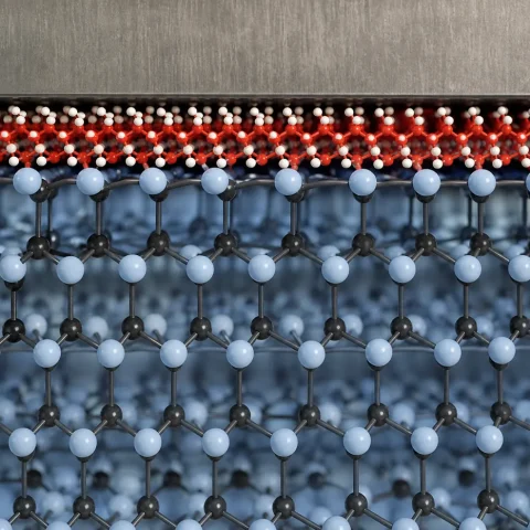
A GaN high-electron-mobility transistor (HEMT) does not use an inversion layer like a silicon MOSFET. Spontaneous and piezoelectric polarization at the AlGaN/GaN interface creates a sheet of electrons, the two-dimensional electron gas (2DEG), at a density of about 1013 cm−2. Because those electrons sit in undoped GaN, impurity scattering is low and mobility reaches about 2,000 cm²/V·s. The result is a small die for a given on-resistance, and a small die means small capacitances.
3. No body diode, no reverse recovery
A silicon MOSFET has a built-in p-n body diode. When it conducts in reverse and then turns off, stored minority charge must be swept out. That reverse-recovery charge (Qrr) adds loss and ringing every cycle in hard-switched bridges. A lateral GaN HEMT has no p-n junction in the current path, so Qrr is zero. It still conducts in reverse, but through the channel, with a higher voltage drop than a silicon diode.
How on-resistance and gate charge compare
Designers compare switches with a device figure of merit: on-resistance multiplied by gate charge, written RDS(on) × Qg and measured in mΩ·nC. Lower is better. It captures the trade-off directly: shrink the die to cut Qg and RDS(on) rises, and the reverse is also true. A material that lowers the product lets you reduce both conduction and switching loss at once.
At the same voltage rating and similar RDS(on), GaN HEMT datasheets typically show a gate charge several times lower than silicon MOSFETs, plus lower output charge (Qoss) and zero Qrr. The exact ratio depends on the voltage class, the generation and the vendor, and it changes with each product release. We do not quote a single ratio here. To compare for your design, pull current datasheets for parts at the same rating (for example two 650 V, 50 mΩ-class devices) and compare Qg, Qoss and Qrr at the same test conditions.
The material ceiling is clearer. The Baliga figure of merit (BFOM), ε·μ·Ec3, predicts the lowest possible specific on-resistance for a given voltage (Baliga, Fundamentals of Power Semiconductor Devices). Using the table values above, GaN’s BFOM comes out several hundred to over a thousand times silicon’s, depending on whether you plug in bulk or 2DEG mobility. Commercial GaN devices sit well below that ceiling. Conventional silicon MOSFETs already sit close to theirs, and superjunction designs get past it only by charge-balancing the drift region.
| Device attribute | Silicon MOSFET (incl. superjunction) | GaN HEMT (enhancement-mode) |
|---|---|---|
| Structure | Vertical, current flows through the wafer | Lateral, current flows along the surface |
| Reverse-recovery charge Qrr | Present (body diode) | Zero |
| Gate charge at equal RDS(on) | Higher | Several times lower (datasheet dependent) |
| Typical gate drive | 10–15 V; ±20 V maximum common | About 5–6 V for p-GaN gates; maximum around 6–7 V |
| Avalanche rating | Usually specified | Not avalanche-capable; rated for transient overvoltage instead |
| Main commercial voltage range | Under 30 V to about 900 V | Mostly 15 V to 650 V |
Why GaN is better than silicon for chargers
A USB-C laptop charger is a high-frequency AC-DC converter. Its size is set mostly by the transformer, inductors and capacitors, and their size falls as switching frequency rises. Silicon MOSFETs in these designs are usually held to roughly 100 kHz or below because switching loss climbs with frequency. GaN’s low charge and zero reverse recovery let designers push into the several-hundred-kHz range and beyond at acceptable loss, so the magnetics shrink and the charger gets smaller and runs cooler at the same power.
The same logic applies to data-centre power supplies, 48 V server conversion and LiDAR drivers, where fast edges matter. For a wider view of GaN power applications, see our GaN high-power applications guide.
What is the cost difference?
Per amp of rated current, a GaN transistor still costs more than a silicon MOSFET of the same voltage class. We have not found a public, dated price ratio solid enough to quote, so we keep this qualitative. Three trends are well established:
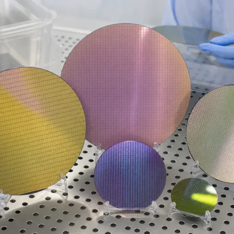
- Most power GaN is grown on silicon wafers (GaN-on-Si), which lets it use existing 150 mm and 200 mm silicon fab lines. That keeps the cost gap far smaller than for GaN-on-SiC. Our GaN-on-Si vs GaN-on-SiC comparison covers the substrate trade-offs.
- The gap has narrowed as volumes rose, driven largely by consumer fast chargers.
- System cost is what counts. Smaller magnetics, smaller heat sinks and fewer parts can offset a pricier switch. In low-frequency designs that offset disappears, and silicon wins on price.
Where silicon still wins
- Ruggedness. Silicon MOSFETs can absorb avalanche energy. GaN HEMTs cannot, so the circuit must clamp overvoltage.
- Gate-drive margin. A silicon gate tolerates ±20 V. A p-GaN gate has only a few volts of headroom above its drive level, so layout and driver choice are less forgiving.
- Dynamic on-resistance. Charge trapping in GaN buffers and surfaces can raise RDS(on) just after high-voltage switching. Modern parts control it well, but it must be checked.
- Low frequency, high current. In motor drives and line-frequency equipment, switching loss is a small share of the total, and silicon’s lower price per amp dominates.
- Above about 650 V. Lateral GaN gets harder to scale. Silicon superjunction devices, silicon IGBTs and SiC MOSFETs dominate there. Our GaN vs SiC guide covers the split by voltage.
Does GaN replace silicon MOSFETs?
Not across the board. GaN is taking sockets where switching frequency, power density or efficiency is the constraint: fast chargers, compact power supplies, 48 V conversion and some motor drives. Silicon keeps the large volume of cost-driven, lower-frequency designs. The likely outcome is coexistence by application, the same pattern seen when silicon IGBTs and MOSFETs split the market by voltage and frequency.
Pick GaN when, pick silicon when
- Pick GaN when you switch above roughly 100 kHz, need the smallest possible magnetics, run hard-switched bridges where Qrr hurts, or work between 40 V and 650 V with power density as the goal.
- Pick silicon when cost per amp dominates, the design switches slowly, the application needs avalanche ruggedness, or the team wants the widest choice of second sources and drivers.
Frequently asked questions
Is GaN faster than silicon because of higher electron mobility?
Only partly. Bulk GaN electron mobility (up to about 1,000 cm²/V·s) is lower than silicon’s (up to about 1,400 cm²/V·s). The speed comes from the 2DEG channel, the roughly 11 times higher critical field and the absence of reverse-recovery charge.
What voltage are GaN transistors rated for?
Most commercial GaN power transistors are rated from about 15 V to 650 V. Higher-voltage GaN exists but is a small share of the market; above 650 V, SiC MOSFETs and silicon IGBTs are the usual choices.
Is GaN made on silicon wafers?
Most power GaN is. Thin GaN and AlGaN layers are grown on silicon substrates by metal-organic chemical vapour deposition, with buffer layers to manage the lattice and thermal mismatch. RF GaN more often uses SiC substrates for better heat removal.
Can I drop a GaN transistor into a silicon MOSFET design?
Rarely. GaN needs a lower, tightly controlled gate voltage, a very low-inductance layout and overvoltage clamping because it has no avalanche rating. Most designs are reworked to take advantage of the higher frequency anyway.
Sources
- Ioffe Institute, New Semiconductor Materials (NSM) archive: Si and GaN property pages. http://www.ioffe.ru/SVA/NSM/Semicond/
- B. J. Baliga, Fundamentals of Power Semiconductor Devices, Springer (Baliga figure of merit and drift-region design).
- S. M. Sze and K. K. Ng, Physics of Semiconductor Devices, 3rd ed., Wiley (MOSFET operation, junction breakdown).
- Review literature on AlGaN/GaN HEMTs and polarization-induced 2DEG formation (2DEG density and mobility ranges).